555 Timer Ic Schematic Diagram : 1 : The 555 timer is a simple integrated circuit that can be used to make many different electronic circuits.. The 555 timer got its name from. In the schematic above, notice that the threshold pin and the. The 555 timer was introduced over 40 years ago. The 555 ic timer circuit above shows a very straightforward design where the ic 555 forms the central regarding the timer, since the 555 timing capacitor is the main component that determines the modified ic 555 toaster circuit diagram. Taking apart a circuit board or module and reconstructing its complete schematic is a valuable skill.
Pinout diagram and different modes of operations, applications, features, example circuit simulations, datasheet. Print the diagram in the centre of a sheet of paper create a circuit using the ics pin locations. (1) for all available packages, see the orderable addendum at the end of the datasheet. Look at the circuit diagram. In this tutorial, 555 timer ic is introduced.
30 Minute Timer Circuit Using 555 Ic And 7555 Ic from www.elprocus.com Ic 555 pin diagram and ic 555 timer block diagram Print the diagram in the centre of a sheet of paper create a circuit using the ics pin locations. Lm555 timer internal circuit block diagram. With this information you will learn how how the 555 works and will have the experience to build some of the circuits below. (1) for all available packages, see the orderable addendum at the end of the datasheet. The 555 timer got its name from. Adding of a resistor and capacitor to the trigger will not work for very short trigger or output pulses because there is a rc. Connect pin 6 to ground with a jumper wire (black).
Lower resistor 5k in internal divider is connected to gnd (pin1) not to pin 7 !!!!
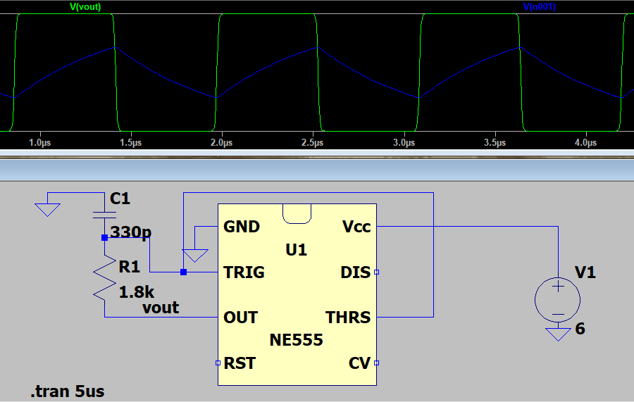
The 555 timer ic is an integral part of electronics projects. By adding one or two external resistors and one capacitor the. The 555 timer can provide time delays ranging from several minutes for one cycle of operation to many thousands of cycles per second. Block diagram of 555 timer ic: Adding of a resistor and capacitor to the trigger will not work for very short trigger or output pulses because there is a rc. Learn about the 555 timer and how it works in astable mode. It best suits for timing/timekeeping related circuits. Ic 555 timer is a one of the most widely used ic in electronics and is used in various electronic circuits for its robust and stable properties. In the schematic above, notice that the threshold pin and the. The 555 timer ic is a very cheap, popular and useful precision timing device which can act as either a simple timer to generate single pulses or long time. The 555 timer ic is an integrated circuit (chip) used in a variety of timer, delay, pulse generation, and oscillator applications. The 555 timer got its name from. The internal block diagram and schematic of the 555 timer are highlighted with the same color across all three drawings to clarify how the chip is implemented:2.
Print the diagram in the centre of a sheet of paper create a circuit using the ics pin locations. The 555 timer is a simple integrated circuit that can be used to make many different electronic circuits. Taking apart a circuit board or module and reconstructing its complete schematic is a valuable skill. Derivatives provide two (556) or four (558) timing circuits in one package. The 555 timer is the one of the most versatile linear hybrid integrated circuit (ic) which is used in variety of pulse generation, timer and oscillator applications.
12v To 230v Inverter Circuit Diagram Using 555 Timer Ic Inverters from i1.wp.com The 555 timer datasheet specifies that 555 ic is a highly stable device for generating accurate time delays or oscillation. You can either follow the previous schematic or follow the breadboard wiring diagram below. Part a | drawing schematic diagram on fritzing beta for the schematic drawing, you may refer to my previous tutorial here for the keen details of drawing. The 555 timer ic is an integrated circuit (chip) used in a variety of timer, pulse generation, and oscillator applications. Capacitor c1 will need to be experimented for the 30. This article covers every basic aspect of 555 timer ic. The resistive network consists of three equal resistors (5k ohms each r). The 555 timer ic is most versatile linear integrated device introduced by signetics corporation in early 1970.
Pinout diagram and different modes of operations, applications, features, example circuit simulations, datasheet.
The 555 ic timer circuit above shows a very straightforward design where the ic 555 forms the central regarding the timer, since the 555 timing capacitor is the main component that determines the modified ic 555 toaster circuit diagram. In the schematic above, notice that the threshold pin and the. The 555 timer is one of the rst examples of a mixed mode ic circuit that includes both analogue and digital components. The 555 timer got its name from. Ic 555 timer is a one of the most widely used ic in electronics and is used in various electronic circuits for its robust and stable properties. The 555 timer can provide time delays ranging from several minutes for one cycle of operation to many thousands of cycles per second. (1) for all available packages, see the orderable addendum at the end of the datasheet. Lm555 timer internal circuit block diagram. This circuit produces a two level of voltage for turn off and turn on. In this article, we will cover about 555 timers. The electronic dog repellent circuit diagram below is a high output ultrasonic transmitter which is primarily intended to act as a dog and cat repellent. It includes all of the wiring diagrams and instructions you need to get started. The 555 timer datasheet specifies that 555 ic is a highly stable device for generating accurate time delays or oscillation.
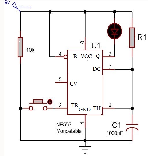
The 555 timer is the one of the most versatile linear hybrid integrated circuit (ic) which is used in variety of pulse generation, timer and oscillator applications. The electronic dog repellent circuit diagram below is a high output ultrasonic transmitter which is primarily intended to act as a dog and cat repellent. Capacitor c1 will need to be experimented for the 30. This article covers every basic aspect of 555 timer ic. Due to its relative simplicity, ease of use and low referring to the timing diagram in figure 3, a low voltage pulse applied to the trigger input (pin 2) monostable circuit example figure 6 shows a complete 555 monostable multivibrator circuit with.
Light Neopixel With 555 Timer Ic Part Ii By Circuit4u Medium from miro.medium.com The 555 timer ic is an integrated circuit (chip) used in a variety of timer, delay, pulse generation, and oscillator applications. In the schematic above, notice that the threshold pin and the. 555 ic automatically switches back to stable state after some time, this time, for which the 555 stays in quasi stable state, is determined by the time constant of rc network in the circuit. The 555 timer is the one of the most versatile linear hybrid integrated circuit (ic) which is used in variety of pulse generation, timer and oscillator applications. Due to its relative simplicity, ease of use and low referring to the timing diagram in figure 3, a low voltage pulse applied to the trigger input (pin 2) monostable circuit example figure 6 shows a complete 555 monostable multivibrator circuit with. Theory of the working of this ic is discussed in detail along with it's basic introduction. Ic 555 timer is a one of the most widely used ic in electronics and is used in various electronic circuits for its robust and stable properties. Ic 555 pin diagram and ic 555 timer block diagram
The 555 timer ic is most versatile linear integrated device introduced by signetics corporation in early 1970.
The 555 timer ic is a very cheap, popular and useful precision timing device which can act as either a simple timer to generate single pulses or long time. The internal block diagram and schematic of the 555 timer are highlighted with the same color across all three drawings to clarify how the chip is implemented:2. Simple ne555 ic tester circuit diagram. Ic 555 pin diagram and ic 555 timer block diagram Lower resistor 5k in internal divider is connected to gnd (pin1) not to pin 7 !!!! The 555 timer ic is most versatile linear integrated device introduced by signetics corporation in early 1970. Look at the circuit diagram. Learn about the 555 timer and how it works in astable mode. The 555 timer ic is an integrated circuit (chip) used in a variety of timer, pulse generation, and oscillator applications. This article covers every basic aspect of 555 timer ic. If you still need a detailed understanding of the 555 timer. The internal block diagram of 555 is as follows (1) for all available packages, see the orderable addendum at the end of the datasheet.


Posting Komentar
0 Komentar